
Update: The coffee alarm system no longer work like described below. The non-coffee-club office neighbors moved out, so we changed from a manual to an automatic system. We've reprogrammed a wifi power plug to notify the system when the coffee maker is turned on. The good old button described below is still operational, but now listens for events over MQTT and does the LED light dance when a new pot is brewing.
We have a Slack integrated coffee notification service at work. It's basically just a few lines of Clojure w/ PostgreSQL (for brew logs and stats), notifying our Slack channel whenever someone put on a brew. It recently got upgraded with a WiFi-connected hardware button button, and now the system operates like this:
So.. how was this made? Let's start with a few of the requirements. Originally I wanted this to be automatic - maybe triggered by an inductive current-sensor connected to the coffee-maker - but since not everyone on the office floor is part of the light-roast-brew-slack-club we decided to go with an Internet connected button to avoid false alarms.
Requirements:
- Triggered via a big physical button.
- Notify office floor via slack:
- Connect to WiFi
- Do HTTP POST to a service running on heroku.
- Battery powered.
- Power down after use to conserve battery power.
- Made only using parts I have available. I do not want to wait to complete this project, so we're just going to wing it.
It makes a lot of sense to base this project on an ESP8266. It's a newish Chinese chip that's been quickly gaining traction with hardware hackers. 80 MHz 32 bit RISC CPU, integrated 802.11 b/g/n WiFi, reasonable amount of IO options. Best of all, it costs less than $5, and if you ask me, it's the first real glimpse of the promised Internet-of-Things wave (or should I say tsunami?). Internet connected 80 MHz CPUs (at the cost of a couple of dollars each) mean they can be added to everything - including your toaster.
Let's get building!
Power
I want the project to be battery-powered (by a 18650 li-ion cell), sadly the ESP8266 is quite power hungry while connected to WiFi. We could have the module stay in deep sleep most of the time, but I want to eliminate as much power drain as possible, so instead, we're going to power down the entire circuit, and only power the module when the big red button is pressed.
If we wire the button between our battery and the ESP8266, it will power up while the button is pressed, and power back down when the button is released. However, connecting to WiFi, receiving an IP via DHCP, doing a HTTP POST, etc - could take like 20-30 sec+ on a bad day, and I'm not going to stand around holding a big red button for 30 sec every time I make a pot of coffee.
We need a latch, a circuit that once triggered stays powered. And we also want the module to power down the circuit after finishing its' duties. Let's build a..
Soft Latch Power Switch
Latches are often made using a P-channel MOSFET and NPN transistor pair. Sadly, I only have big N-channel MOSFETS available. So let's try to make one using a PNP and NPN-transistor pair instead.
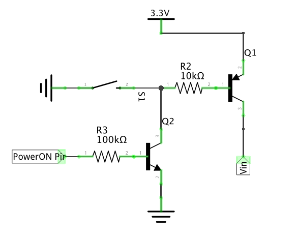

The theory is as follows. Hitting the button will connect the base of the PNP transistor (Q1) to ground, the transistor will start to conduct, thus powering the micro-controller. Once booted, the micro-controller should immediately put one of it's GPIO pins high, GPIO pin will be connected to the base of NPN transistor (Q2). This will take over the role of the button and circuit will continue conducting until micro-controller sets GPIO pin low - at which point everything powers down.
Problems and solutions
Turns out the circuit works, but the ESP8266 has a pretty slow boot-time before pin is set high (1+ sec - WiFi calibration?). Meaning it works if you press and hold the button for at least 1-2 second. This is a problem, we need to give the micro-controller more time to finish booting before it can take over control of the power flow. I'm a programmer, not a miracle analog magician, but let's see if we can't figure this one out. We need power flow to continue through the base of Q1 for some time even after a very short button press, and how can we do that? We can try adding a capacitor right after the R2 resistor. In theory, when the button connects that part of the circuit to ground, power should flow quickly from the capacitor. Once button is released, power will flow slowly back into capacitor (through R2 resistor and Q1's base), keeping Q1 active for a while until the micro-controller can take over.
We add an overkill 1000uF capacitor, and it works. Now even a really short button press keeps the micro-controller powered for several seconds.
Voltage regulation
The ESP8266 can't really handle voltages above ~3.6v without risking damage, and I want to power the circuit from a regular 18650 li-ion cell (the battery cells often used in laptops, and even in the Tesla cars). Li-ion cells have a max voltage of 4.2v and a working voltage of ~3.7v. This turned out to be a bit of a problem, because I didn't really have any suitable voltage regulators laying around. I've a few AMS1117 3.3v, but their drop-out voltage (~1) is simply too much when running from a 3.7v cell.
What I really need is something like a MCP1702, but I don't want to wait around for parts - we're going to run unregulated from a partially depleted 18650. Hopefully I remember to not charge it all the way up if it ever gets depleted :) I might add a MCP1702 or similar modern LDO later.
Spinning LED indicator
My big red button from sparkfun comes with a single led, I want more, I want to add 3 so that I can display a spinning animation while the button is busy. I'm going to steal a few of Andy Frey's ideas, and hack my button similar as his, but with discrete control over each LED.
The ESP8266 can only source like 12 mA current per pin, so to drive the 3 LEDs I add a ULN2003A. The ULN2003A is a NPN (darlington) transistor array, so instead of adding discrete transistors we get 7 of them in one package. Connect 3 GPIO from the ESP8266 to the transistor array's base side, and 3 LEDs (with resistors) to the collector side. This leaves 4 transistors for future expansion.
To make a spinning led indicator we'll use the Ticker library to receive a callback every 0.2 seconds or so.
Ticker spinticker;
unsigned int spincount;

void spinLEDs() {
    spincount++;

    for (int led = 0; led < LEDCOUNT; led++) {
        if (spincount % LEDCOUNT == led) {
            digitalWrite(LEDPINS[led], HIGH);
        } else {
            digitalWrite(LEDPINS[led], LOW);
        }
    }
}

spinticker.attach(SPININTERVAL, spinLEDs);
Enclosure

I didn't really have any suitable sized electronic boxes laying around, only an ugly junction box. I hate ugly beige boxes, so, let's at least give it some color. Spray painted red looks OKish I guess.
Code
Next up, let's add a bit of code to make it work properly, it's all available on github at revolverhuset/mokkameister and revolverhuset/mokkameister-button. But let's have a look at the important stuff here anyway, it's quite small.
ESP8266
On the micro-controller we connect to wifi at the push of the button, and then do a simple hand crafted HTTP request. We also send an auth token, doesn't really add that much security since we're not doing HTTPS, but it's better than nothing I guess.
const char* host = "myservice.herokuapp.com";
const char* path = "/coffee-button/";
const int httpPort = 80;
const char* secret = "secret";

boolean notifyButtonPush() {
    WiFiClient client;

    if (!client.connect(host, httpPort)) {
        return false;
    }

    client.print(String("POST ") + path + " HTTP/1.1\r\n" +
                 "Host: " + host + "\r\n" +
                 "Content-Type: application/x-www-form-urlencoded\r\n" +
                 "Connection: close\r\n"
                 "Content-Length: " + String(7 + String(secret).length) + "\r\n" +
                 "\r\n" +
                 "secret=" + secret + "\r\n" +
                 "\r\n");

    while(client.available()){
        String line = client.readStringUntil('\r');
    }

    client.stop();
    return true;
}
Heroku/Clojure service
Over at heroku we then create simple liberator resource that does something like the following: Validate token, persist brew-data to db, notify slack, wait 5 minutes, notify slack again. We do the waiting in an core.async go-thread.
(defn valid-button-token? [ctx]
  (let [secret (get-in ctx [:request :params :secret])]
    (= secret (env :button-secret))))

(defn button-post! [_]
  (db/persist-brew! ... brewdata ...)
  (go (slack/notify! "Good news everyone! Coffee is brewing!")
      (<! (timeout (* 5 60 1000)))
      (slack/notify! "Coffee is ready!"))
  "OK")

(defresource coffee-button
  :available-media-types ["text/plain"]
  :allowed-methods [:post]
  :authorized? valid-button-token?
  :post! button-post!)
Mount the resource on a suitable route, and be sure to add the default ring api-middleware (so that params are parsed).
Conclusion
Overall it's been a fun tiny side-project, I need to do more of these. Often I want to make something, order up the parts - but when they arrive one month later I've already moved on to other things - so I'm def going to build more with the parts I've at hand, even if they aren't optimal. Also, having a tiny assortment of ESP8266s around is awesome, they are quite useable for things you would want to Internet-able without much effort..

Oh.. and we seems to have a robot infestation problem (again..) :(